
Built-up edge on ductile alloys
Soft 6061 chips can weld to the tool and degrade finish. Control: coated carbide geometry, directed coolant, and planned tool cycles for clean cosmetic faces.
Use aluminum when the part needs to stay light, machine cleanly, and take a finish. Start with 6061-T6 or 7075/7050, then confirm temper, stock, and critical features in DFM.
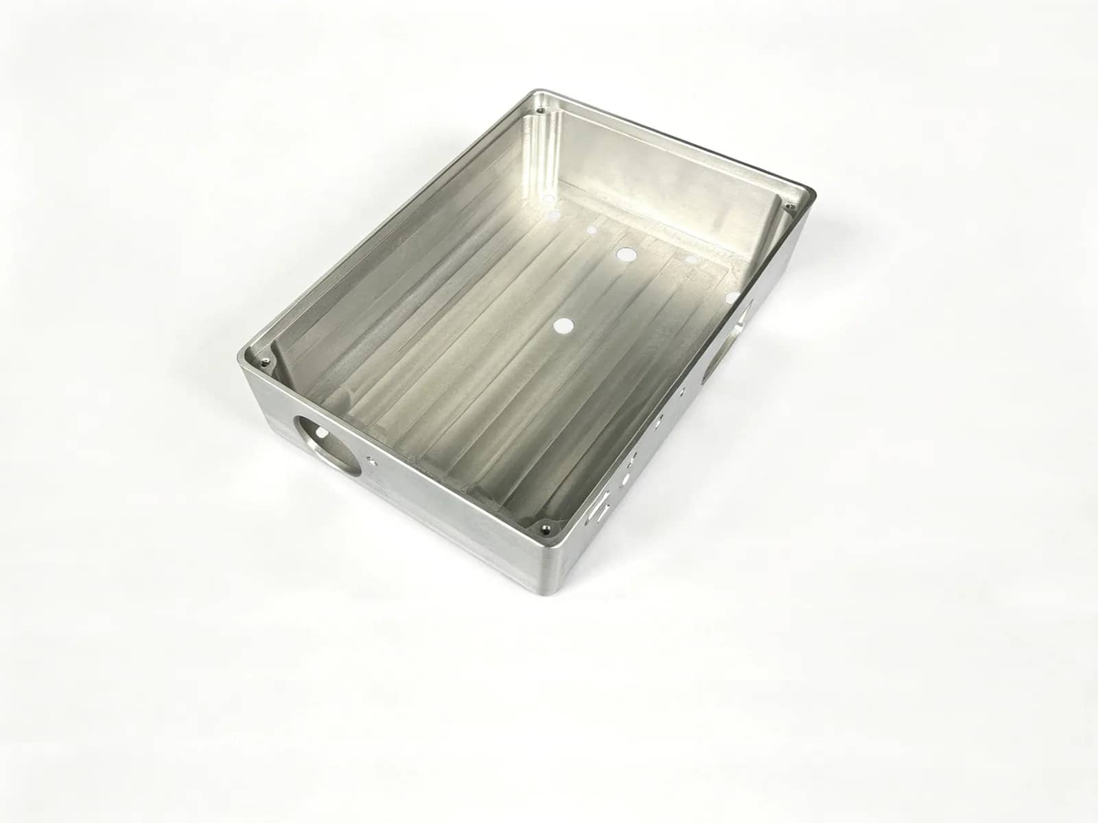
Choose aluminum when the part needs a strong, light structure, good thermal conductivity, or a finish-ready cosmetic face. Typical work includes electronic enclosures and heat-spreading housings, automation brackets and fixture plates, and loaded links in robots or motion stages.
Start with 6061-T6 for general structures and 7075 / 7050 when specific strength matters more. 5052, 2024, and other tempers are quoted only after review of temper, stock form, availability, geometry, and finish.
Match the process to the drawing: milling for pockets and thin walls, turning for round features, and five-axis where a single setup earns its cost. When the drawing is silent, the common default tolerance is ±0.10 mm; tighter limits are confirmed via DFM.
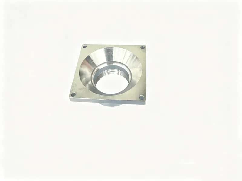
Reliable starting point for enclosures, brackets, and fixture plates — efficient machining, corrosion resistance, and anodize-friendly faces when cosmetic requirements are clear.
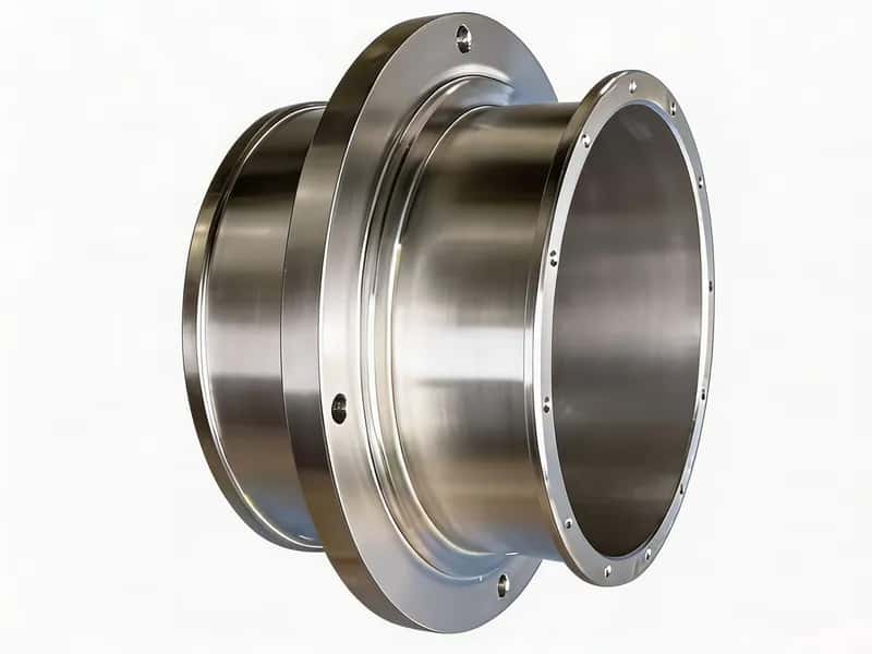
Higher strength-to-weight for loaded housings, flanges, and motion hardware. Plan residual-stress control and staged rough-to-finish before locking critical datums.
| Grade | Choose it when | Machining watch-outs | Typical tolerance posture | Compatible finishes |
|---|---|---|---|---|
| 6061-T6 | Enclosures, fixtures, and general hardware where machining and corrosion resistance beat peak strength | Built-up edge; soft faces mark in hard jaws; thin walls move under heat or clamp load | ±0.10 mm default; ±0.01 mm on selected rigid features after DFM | Type II/III anodize, blast, conversion coat — coordinated; allow coating build-up |
| 7075 / 7050 | Loaded robot links and high-stress brackets that need higher specific strength | Stress release after roughing; faster tool wear; distortion on large flats or thin sections | ±0.10 mm default; ±0.01 / ±0.005 mm only where grade, geometry, and DFM allow | Hard anodize, blast, precision deburr — coordinated; mask critical fits |
Soft 6061 chips can weld to the tool and degrade finish. Control: coated carbide geometry, directed coolant, and planned tool cycles for clean cosmetic faces.
Soft alloys scratch under hard jaws. Control: soft jaws or pads, clean workholding, and protecting anodize-critical faces through the process plan.
Heat and clamp load warp thin walls and large flats. Control: symmetric roughing, flood cooling, modulated clamp force, and room-temperature metrology.
7075/7050 can move after roughing and wear tools faster. Control: rough → semi-finish → finish with finishing allowance after stress stabilizes.
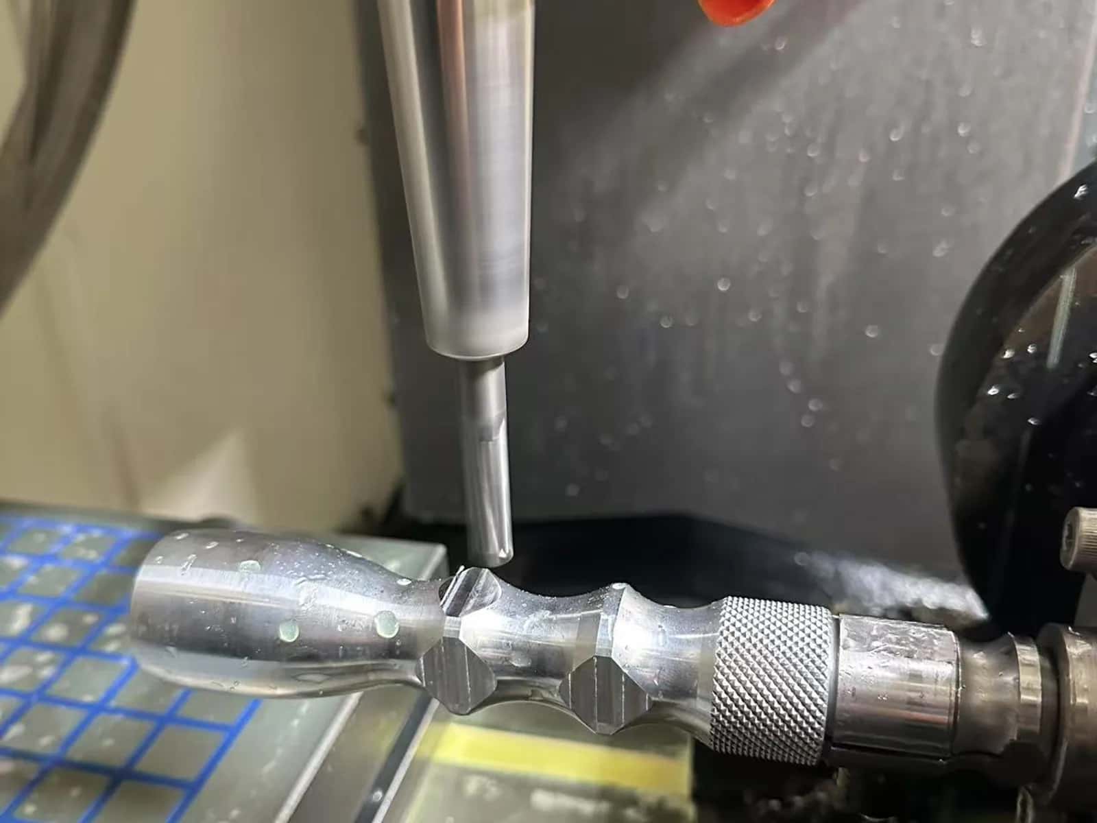
Live-tool milling on aluminum bar and shaft work shows the chip control and fixturing used on production cells. Finished housings and flanges on this page are production photography for grade selection, not a named customer program.
Aluminum holds size more readily than many plastics, but temper, residual stress, and thin walls still move parts. ±0.10 mm is the common default when a metal drawing is unspecified. ±0.01 mm and ±0.005 mm apply only to selected features where material and geometry allow and DFM or the drawing confirms them — not as blanket commercial defaults. Rigid 6061 features are often easier to hold than stress-sensitive 7075 sections.
In-house CNC machining and agreed-scope pre-shipment inspection verify critical characteristics. "100% inspection" means the agreed characteristic scope, not CMM of every feature. FAI, MTR, CoC, and material traceability are available when agreed for the project. Metrology can include ZEISS SPECTRUM CMM, optical comparators, and spectrometers when required. See Precision & Tolerance Standards and Quality Control.
Type II and Type III anodizing, blasting, deburring or polishing, and conversion coatings are available or coordinated per project. Specify coating type, color, masking, and dimensional build-up on critical fits. Hardware inserts and light assembly can be included in the same order when specified. Details: CNC surface finishes.
Send a package that lets engineering quote without guessing:
Upload CAD via Request a Quote. The Material field can be prefilled and remains editable.
Upload CAD for DFM review with aluminum context prefilled. We typically respond within one business day when the package is complete.