
General fillet radius
Prefer ≥ 0.5 mm on most parts; 1.0–2.0 mm on larger or higher-stress features. Match the minimum internal radius to the end-mill radius you expect (often 0.2–0.5 mm tools).
Practical DFM rules for walls, holes, fillets, and drawings — so your CAD is ready for quoting and machining.
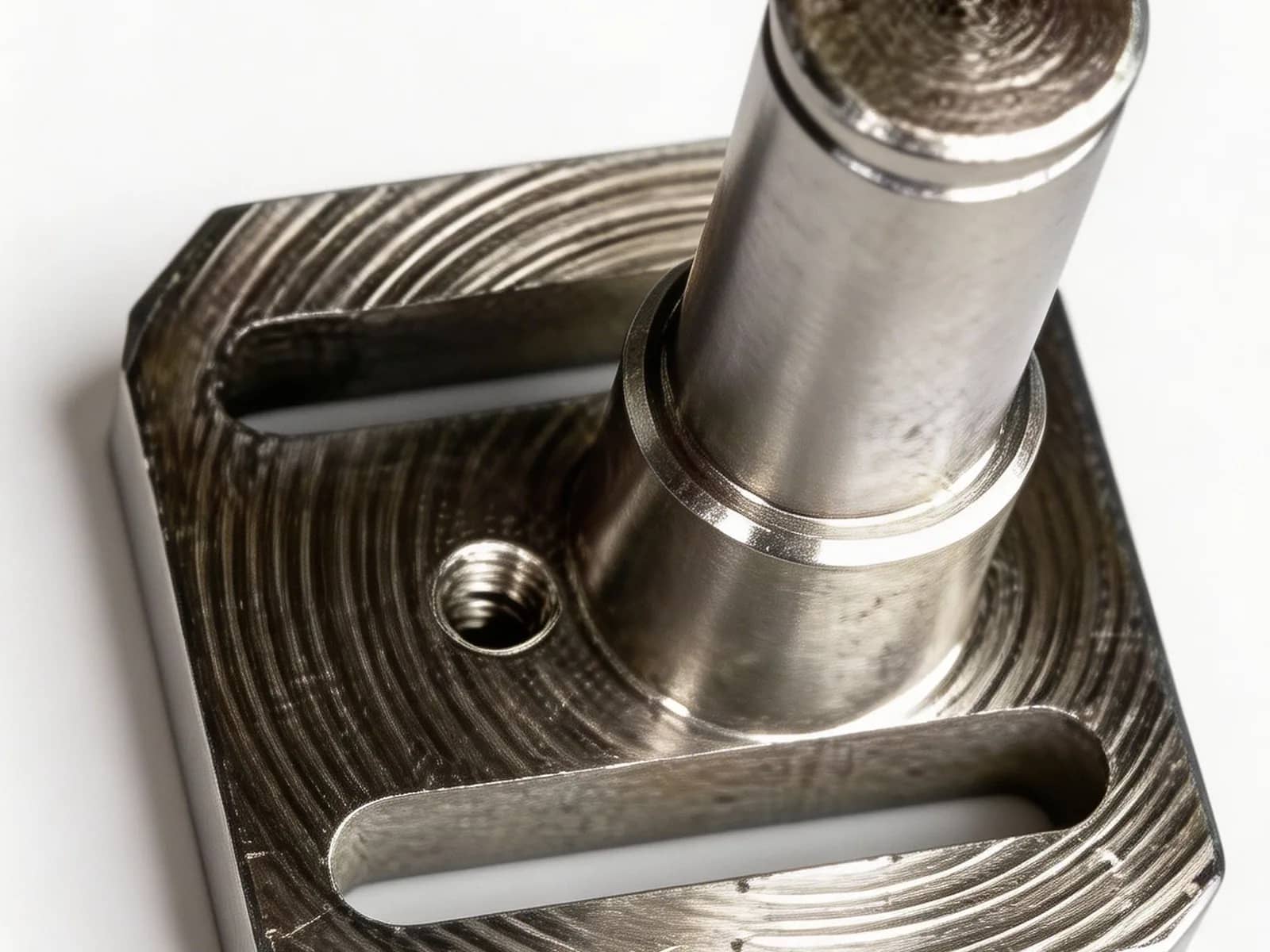
Use this guide when you are freezing geometry for CNC milling or turning and need manufacturable walls, holes, corners, and drawing packages before you request a quote.
It is a starting checklist for common metals and engineering plastics — not a substitute for drawing review. Edge cases (very deep pockets, micro features, exotic alloys, or cosmetic Class-A faces) still need a free DFM pass when you upload CAD.
When a metal drawing is silent on size, our common default delivery is ±0.10 mm. Prefer ISO 2768-m for non-critical features and call out tighter limits only where function requires them (Precision & Tolerance Standards).
| Material type | Recommended minimum wall | Notes |
|---|---|---|
| Aluminum (6061, 7075, 5052) | 0.8 – 1.0 mm | If wall height exceeds ~5× thickness, add ribs or reduce height to limit chatter and clamp distortion |
| Stainless steel (304, 316) | 1.0 – 1.2 mm | Harder stock — thin walls vibrate and deflect more readily |
| Carbon steel (45#, 1045) | 1.0 – 1.2 mm | Keep thickness appropriate for structural strength |
| Engineering plastics (PEEK, POM, PPS) | 0.6 – 0.8 mm | Good toughness, but avoid paper-thin sections that crack in assembly |
Keep wall thickness as uniform as practical. Large thickness jumps create uneven heat and residual stress. If thin walls are unavoidable, add fillets at transitions and reinforcing ribs where the function allows.
| Depth / diameter ratio | Min Ø (metals) | Min Ø (plastics) | Notes |
|---|---|---|---|
| ≤ 3:1 | 1.0 mm | 0.8 mm | Through-hole baseline; blind holes often need +0.2–0.3 mm |
| 3:1 – 5:1 | 1.5 mm | 1.2 mm | Chip evacuation becomes harder |
| 5:1 – 10:1 | 2.0 mm | 1.5 mm | Risk of tool deflection and breakage rises |
| Deep hole (> 10:1) | ≥ 3.0 mm | ≥ 2.5 mm | Plan specialty tooling or staged drilling |
For blind holes, design a bottom fillet (radius ≥ 0.5 mm) where possible. For threaded holes, leave adequate minor diameter and use standard Metric or UNC pitches — custom threads add cost and lead time.
Prefer ≥ 0.5 mm on most parts; 1.0–2.0 mm on larger or higher-stress features. Match the minimum internal radius to the end-mill radius you expect (often 0.2–0.5 mm tools).
Cutting tools have radius — absolute sharp internal corners leave residual stock or need EDM. Sharp corners also concentrate stress under load or vibration.
Use fillets (≥ 0.5 mm) or 45° chamfers (0.5–1.0 mm). If a sharp external corner is functionally required, call it out on the drawing so we plan the tool strategy.
On mating faces, size fillets so they do not interfere with fit. On load-bearing parts, larger fillets disperse stress and improve fatigue life.
Preferred 3D solid for toolpaths. Compatible with mainstream CAD and retains geometry accurately.
Useful for complex surfaces when STEP is unavailable.
2D for critical dimensions, tolerances, roughness, material, and finish notes. PDF alone is not enough for complex 3D parts.
Mark datums, critical fits, surface finish, and any masking for coatings. Ambiguity becomes scrap or RFQ delay.
Chatter, clamp marks, and scrap rise when height-to-thickness or depth-to-width ratios force slow feeds or specialty tooling.
Absolute sharp internal corners require EDM or leave leftover stock — schedule and cost jump if the drawing never called them out.
Missing datums, finish notes, or hole-callouts force conservative quotes, RFQ back-and-forth, or wrong-first-article risk.
Blanket tight tolerances multiply cycle time and inspection. Apply tight bands only where function needs them.
Upload the package via Request a Quote. With a complete RFQ we typically respond within one business day.
Upload your CAD files for a free DFM review and quotation. We typically respond within one business day.