
Multi-axis process fit
Match 3-, 4-, or 5-axis milling to faces, undercuts, and setup count — confirmed in DFM, not a one-size claim.
3-, 4-, and 5-axis CNC milling for robotics, automation, and industrial assemblies — deep cavities, thin walls, and multi-face parts with DFM before we cut.
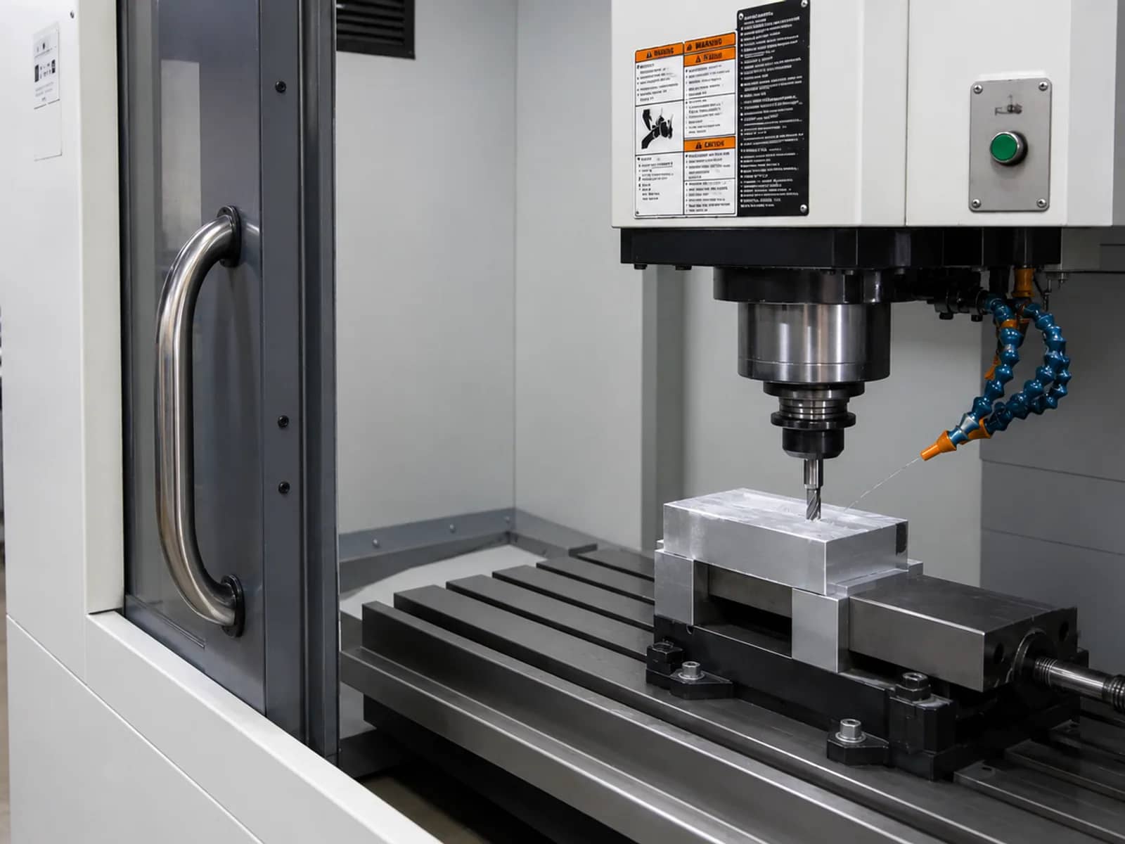
Match 3-, 4-, or 5-axis milling to faces, undercuts, and setup count — confirmed in DFM, not a one-size claim.
Standard delivery ±0.10 mm unless the drawing specifies otherwise. Selected features can reach ±0.01 mm where material and geometry allow.
In-house metrology including ZEISS CMM. Pre-shipment scope follows the drawing and agreed plan; FAI and reports on request.
CNC milling for prismatic and multi-face metal and engineering-plastic parts — pockets, contours, thin walls, fixture-critical datums, and mating interfaces. We select 3-axis, indexed 4-axis, or 5-axis based on tool access and setup economy, then lock the plan in DFM before quoting. Secondary finishes and hardware assembly are available under the same project when needed.
Upload STEP/IGES and 2D PDF for critical dimensions, GD&T, and finish notes.
We check radii, pocket ratios, thin walls, tool access, and tolerance economy before locking the quote.
Stock, fixtures, and axis strategy selected for geometry and grade.
Programmed toolpaths on multi-axis centers with in-process checks at setup changes.
Dimensional verification per drawing — CMM and hand tools as required.
Protected packaging and documentation aligned to the purchase order.
| Item | Capability |
|---|---|
| Processes | 3-axis, 4-axis, and 5-axis CNC milling; pocketing, contouring, drilling, tapping |
| Materials | Aluminum, steels, stainless, copper alloys, titanium (suitable grades), engineering plastics — see material pages |
| Typical tolerance | ±0.10 mm standard delivery when unspecified; ±0.02–0.05 mm and ±0.01 mm on selected features where design allows — confirmed via DFM |
| Critical features | Tighter limits (including ±0.005 mm on designated 5-axis features) evaluated case-by-case per drawing and confirmed via DFM |
| Work envelope (ref.) | Up to about 800 × 600 × 500 mm on multi-axis centers — confirm per part |
| File formats | STEP / STP, IGES, and 2D PDF drawings strongly recommended for critical dims |
| Inspection options | In-house CMM and shop metrology; FAI and reports on request; scope per drawing |
6061, 7075, and related alloys for structural and enclosure parts.
Carbon, alloy, stainless, and tool steels with process planning for hardness.
Copper, brass, and bronze for conductivity and thermal parts.
POM, PEEK, PTFE, nylon, and other engineering polymers.
Anodizing, plating, bead blast, and related finishes with dimensional notes.
Compare grades, machinability, and selection tips.
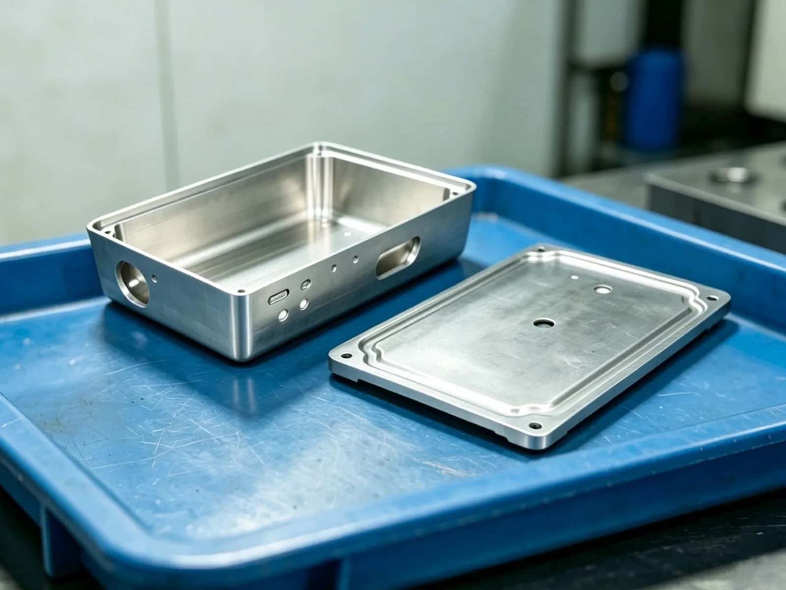
Milled housings and cover plates show pocketed interiors, sealing faces, and side ports typical of enclosure and interface work. Fixturing and tool access are planned so mating faces stay consistent across setups — the same discipline we apply to thin walls and deep cavities.
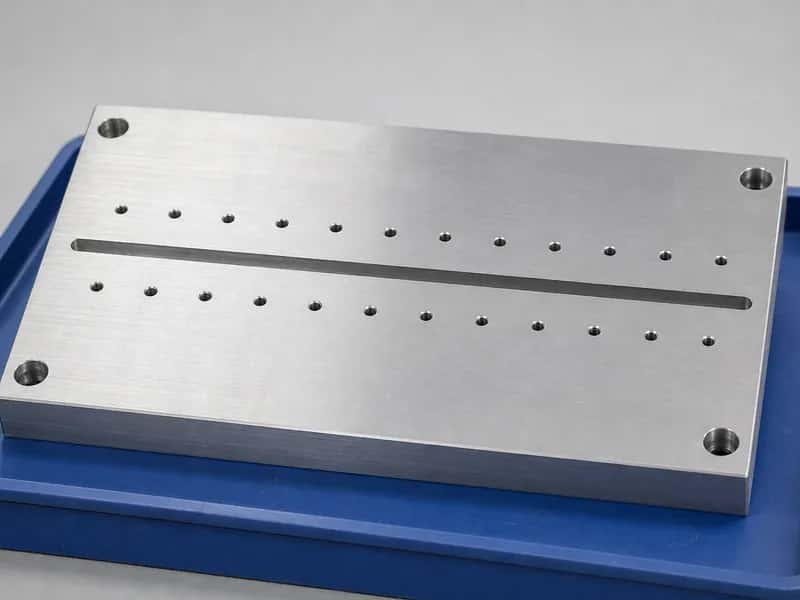
Slotted locating plate with patterned holes for repeatable workholding and multi-face setups.
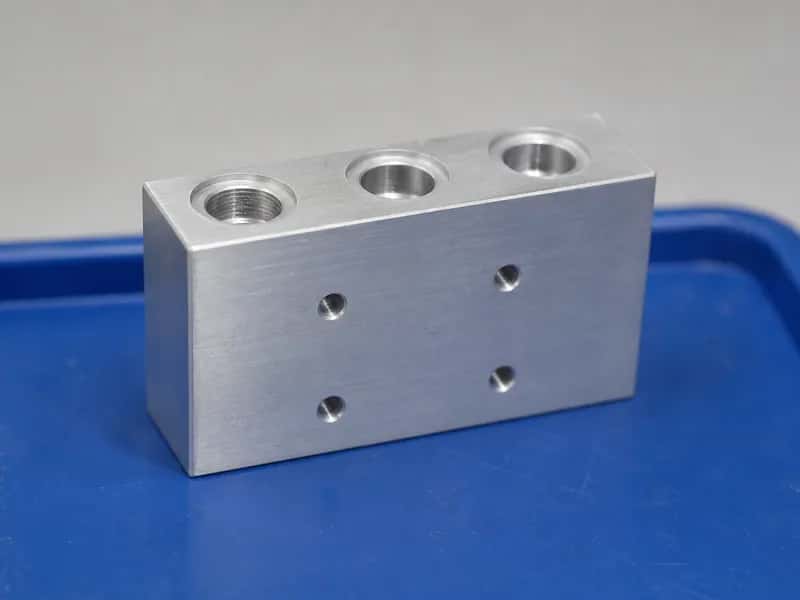
Counterbored ports and front mounting holes for electromechanical and fluid interfaces.
Project limits are always per drawing and confirmed via DFM before we commit a quote. In-house inspection supports ZEISS CMM measurement and calibrated hand tools. Pre-shipment verification follows the agreed inspection plan — not an unconditional promise on every feature of every part. Optional FAI and material documentation (MTR) are available on request. Full QC narrative: CNC machining quality control.
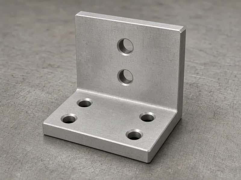
Housings, brackets, and interface blocks where multi-face accuracy and repeatable fits matter — industry relevance only, not a certification claim.
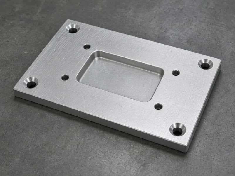
Fixtures, manifolds, and structural milled parts for production machinery.
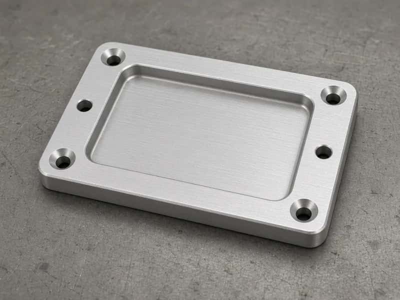
Precision plates, covers, and thermally relevant metal/plastic components.
Use 3-axis for prismatic parts with primary access from one or two setups. Add 4-axis when indexed faces reduce refixturing. Choose 5-axis when undercuts, compound angles, or single-setup multi-face accuracy justify the process — we confirm fit during DFM.
Standard delivery is ±0.10 mm on typical milled features unless the drawing specifies otherwise. High-precision ±0.02–0.05 mm and ±0.01 mm on selected features are available where material and geometry allow — confirmed via DFM before quoting.
We review CAD for internal corner radii, pocket depth-to-width ratios, thin-wall stability, hole/thread accessibility, and which tolerances are functionally necessary versus costly to hold.
Upload your CAD files for a free DFM review and quotation. We typically respond within one business day.