
CAD design
Define geometry with DFM in mind — walls, fillets, and tool access. Request a free DFM review before production if unsure.
A plain-language overview of CNC processes, when to use milling, turning, multi-axis, and EDM, and how they fit together from CAD to delivery.
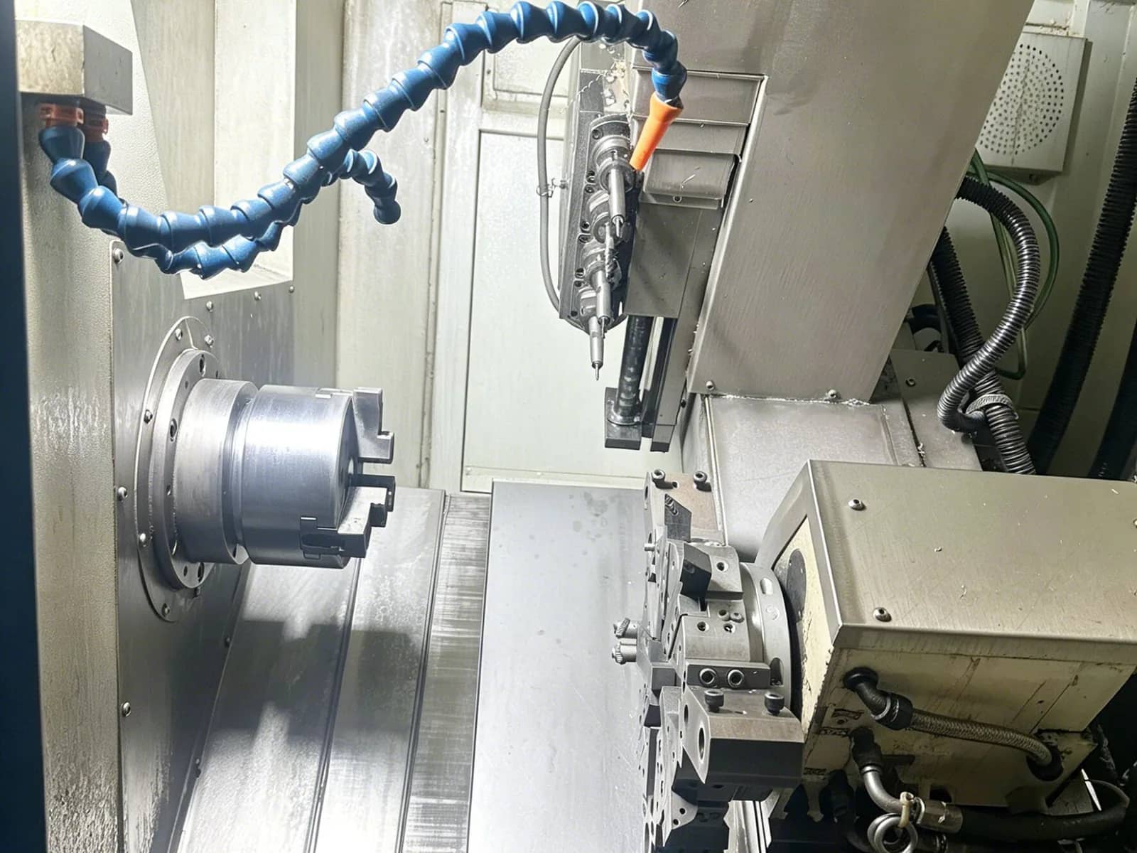
Use this guide when you need a process-level map of CNC machining — what subtractive manufacturing is, how a job moves from CAD to delivery, and which machine type fits common geometries.
CNC (Computer Numerical Control) machining uses programmed toolpaths to cut parts from solid stock. Compared with hand operation, it improves repeatability on complex geometry and scales from one prototype to production. MOQ is 1; with a complete RFQ we typically respond within one business day.
It is a subtractive process: material is removed as chips. CNC is a strong fit when you need solid-material properties, good as-machined surfaces, and dimensional control. Delivery defaults are typically ±0.10 mm when unspecified; tighter ±0.01 mm / ±0.005 mm claims apply only on designated features when material, geometry, and DFM allow — not as a blanket promise on every PO.
| Type | How it works | Examples | Vs CNC |
|---|---|---|---|
| Subtractive (CNC) | Removes material from solid stock | Milling, turning, drilling, EDM | Strong finish and tolerances; chip waste |
| Additive | Builds layer by layer | FDM, SLA, SLS, DMLS | Internal lattices easier; usually rougher; different density |
| Formative | Shapes with a mold or die | Injection molding, casting, forging | Fast at volume; high tooling cost; slower design changes |
Define geometry with DFM in mind — walls, fillets, and tool access. Request a free DFM review before production if unsure.
Program toolpaths, tools, speeds, and strategies. Simulation catches collisions before metal is cut.
Fixture the stock, load tools, set workpiece zero and tool offsets, and verify coolant and chip evacuation.
Rough to leave stock, then finish to size. Multi-axis setups reduce refixturing on complex faces.
Verify critical characteristics per the agreed plan, then deburr, finish, heat-treat, or assemble as ordered.
| Machine | Motion | Typical work | Well suited for |
|---|---|---|---|
| 3-axis milling | X, Y, Z | Pockets, faces, holes, slots | Prismatic parts and simple contours |
| 5-axis milling | X, Y, Z + two rotary | Sculpted surfaces, angled holes | Undercuts and multi-face accuracy in fewer setups |
| CNC turning | X, Z (+ live tooling) | OD/ID, grooves, threads | Shafts, bushings, housings |
| Swiss-type | Sliding headstock multi-axis | Small slender turning | Medical connectors, fine shafts |
| Wire EDM | Wire path in conductive stock | Hard materials, sharp internal corners | Punch/die, intricate profiles after heat treat |
For design rules before you cut: CNC Design Guidelines. For equipment envelope and industries: Our Capabilities.
Compound angles and undercuts forced through repeated refixturing stack datum error and cost — 5-axis or mill-turn may be the economical path.
Round shafts cut mainly on a mill burn cycle time and lose OD consistency that turning delivers more naturally.
Trying to mill hardened tool steel or sharp internals without EDM drives tool wear, schedule risk, or geometry compromise.
Heat treat, finish, or assembly assumed but never ordered — lead time and size control (e.g. hardcoat growth) miss the drawing.
Upload via Upload CAD for DFM Review. With a complete RFQ we typically respond within one business day. MOQ is 1.
Upload your CAD files for a free DFM review and quotation. We typically respond within one business day.